
Simple Alarm
System
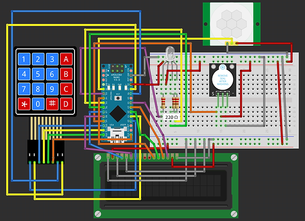
This alarm system uses an Arduino Nano, a PIR motion sensor, an RGB LED, a 16x2 LCD display (parallel connection), a 4x4 keypad, and a buzzer. The system is activated or deactivated using a password entered on the keypad. When motion is detected while the system is armed, the buzzer sounds, and the RGB LED indicates an alert. The LCD displays system status messages.
How It Works
The system starts in a disarmed state. The user enters a 4-digit password using the keypad. Pressing # submits the password. If correct, the system toggles between armed and disarmed mode. If incorrect, the LCD displays an error message. When armed, the PIR sensor detects motion, triggering an alarm with the buzzer and changing the RGB LED color. The LCD displays "Motion Detected!" for feedback. The alarm lasts for 1 second, then resets and continues monitoring.
Materials
To build a simple Arduino Alarm System project with an Arduino Nano, you'll need the following materials:
Components:
1) Arduino Nano
-
The microcontroller that runs the alarm system.
2) PIR motion sensor (HC-SR501)
-
Detects motion and triggers the alarm.
3) Buzzer (Piezo KY-012)
-
Sounds an alarm when motion is detected.
4) RGB LED (4-pin common anode)
-
Provides visual status indicators for armed, disarmed, and alarm states.
5) Resistors (3x 220Ω for RGB LED)
-
Limits current to the LED to prevent damage.
6) 4x4 Keypad
-
Used to enter the password for arming and disarming the system.
7) 16x2 LCD (Parallel, No I2C)
-
Displays system status messages.
8) Jumper Wires
-
Connects components to the Arduino.
9) Breadboard
-
Provides a base for easy prototyping and wiring.
10) USB Cable (Type-A to Type-mini-B)
-
To connect Arduino to a computer for programming and power.
Basic Setup

1) PIR Motion Sensor
-
VCC → 5V (Power line of breadboard)
-
GND → GND (Ground line of breadboard)
-
OUT → Pin 2
2) Buzzer
-
VCC → 5V (Power line of the breadboard)
-
GND → GND (Ground line of breadboard)
-
Signal → Pin 9
3) RGB LED (Common Anode)
-
Anode (+) → 5V (Power line of breadboard)
-
Red → Pin 3 (via 220Ω resistor)
-
Green → Pin 5 (via 220Ω resistor)
-
Blue → Pin 6 (via 220Ω resistor)
4) Keypad (4x4)
-
Rows → A0, A1, 10, 11
-
Columns → 12, 13, A6, A7
5) LCD (Parallel, No I2C)
-
VSS GND (Ground line of breadboard)
-
VCC → 5V (Power line of breadboard)
-
Contrast (VO) → GND (Ground line of breadboard)
-
RS → Pin 7
-
RW → GND (Ground line of breadboard)
-
E (Enable) → Pin 8
-
D0, D1, D2, D3 → Leave disconnected
-
D4 → Pin 4
-
D5 → Pin A2
-
D6 → Pin A3
-
D7 → Pin A4
-
A → 5V (Power line of breadboard)
-
K → GND (Ground line of breadboard)
6) ) Power the Arduino:
-
Connect the Arduino to your computer using the USB cable for power and programming capabilities.
Software Setup
Install Keypad.h and LiquidCrystal.h. These are both native to the Arduino IDE library manager.
1) How to Install the Keypad Library
-
Open the Arduino IDE.
-
Go to Sketch → Include Library → Manage Libraries....
-
In the Library Manager, type "Keypad" in the search bar.
-
Look for "Keypad by Mark Stanley, Alexander Brevig".
-
Click Install.
-
Wait for the installation to complete.
2) How to Install the LiquidCrystal Library
-
Open the Arduino IDE.
-
Go to Sketch → Include Library → Manage Libraries....
-
In the Library Manager, type "LiquidCrystal" in the search bar.
-
Look for "LiquidCrystal by Arduino".
-
Click Install (it may already be pre-installed).
-
Wait for the installation to complete.


CODE BREAK-DOWN
include <Keypad.h>;
include <LiquidCrystal.h>;
-
Adds libraries so the Arduino can use a keypad and LCD screen.
LiquidCrystal lcd(7, 8, 4, A2, A3, A4);
-
Sets up the LCD screen and defines which Arduino pins connect to it.
define PIR_SENSOR 2;
define BUZZER 9;
define RED_LED 3;
define GREEN_LED 5;
define BLUE_LED 6;
-
Assigns pin numbers for the PIR sensor, buzzer, and RGB LED pins.
const byte ROWS = 4;
const byte COLS = 4;
-
Defines how many rows and columns the keypad has.
char keys[ROWS][COLS] = {...};
-
Creates the keypad layout and assigns each button a value (like '1', '2', etc).
byte rowPins[ROWS] = {A0, A1, 10, 11};
byte colPins[COLS] = {12, 13, A6, A7};
-
Assigns Arduino pins to the keypad rows and columns.
Keypad keypad = Keypad(makeKeymap(keys), rowPins, colPins, ROWS, COLS);
-
Creates the keypad object so the Arduino can detect key presses.
String inputPassword = "";
String correctPassword = "1234";
bool systemArmed = false;
-
Stores the user’s entered password, the correct password, and whether the system is armed or not.
setRGB(int r, int g, int b);
-
Creates a function to set the RGB LED colour. It uses inverted values because the LED is common anode.
analogWrite(RED_LED, 255 - r);
analogWrite(GREEN_LED, 255 - g);
analogWrite(BLUE_LED, 255 - b);
-
Controls the brightness of each colour in the RGB LED.
setup();
-
Starts the setup, which runs once when Arduino powers on.
pinMode(PIR_SENSOR, INPUT);
pinMode(BUZZER, OUTPUT);
pinMode(RED_LED, OUTPUT);
pinMode(GREEN_LED, OUTPUT);
pinMode(BLUE_LED, OUTPUT);
-
Sets the pins as input or output.
Serial.begin(9600);
-
Starts serial communication for debugging purposes.
lcd.begin(16, 2);
lcd.setCursor(0, 0);
lcd.print("Enter Password:");
-
Initialises the LCD and prints "Enter Password".
setRGB(0, 255, 0);
-
Sets RGB LED to green which means system is disarmed.
loop();
-
This is the main repeating program loop.
char key = keypad.getKey();
-
Reads if any button on the keypad is pressed.
if (key);
-
If a button was pressed, do the following.
lcd.setCursor(inputPassword.length(), 1);
lcd.print('*');
-
Displays * on LCD for each key entered to hide password.
if (key == '#');
-
If # is pressed, user is submitting password.
if (inputPassword == correctPassword);
-
If entered password is correct, toggle system armed/disarmed.
systemArmed = !systemArmed;
-
Switches armed state.
lcd.clear();
lcd.setCursor(0, 0);
lcd.print(systemArmed ? "System Armed" : "System Disarmed");
-
Displays armed or disarmed status on LCD.
if (systemArmed);
setRGB(0, 0, 255);
-
If armed, set RGB LED to blue.
else
setRGB(0, 255, 0);
-
If disarmed, set RGB LED to green.
delay(2000);
lcd.clear();
lcd.setCursor(0, 0);
lcd.print("Enter Password:");
-
Wait 2 seconds, then show password prompt again.
else (wrong password)
lcd.clear();
lcd.setCursor(0, 0);
lcd.print("Wrong Password!");
delay(2000);
lcd.clear();
lcd.setCursor(0, 0);
lcd.print("Enter Password:");
-
If password is wrong, show error for 2 seconds, then ask again.
inputPassword = "";
-
Clears entered password after submit.
else if (key == '*');
-
If * pressed, clear the password entry.
inputPassword = "";
lcd.clear();
lcd.setCursor(0, 0);
lcd.print("Enter Password:");
-
Resets password input and asks again.
else if (inputPassword.length() < 4);
-
If password is less than 4 characters, add pressed key.
inputPassword += key;
-
Add the key press to password input.
if (systemArmed && digitalRead(PIR_SENSOR) == HIGH);
-
If system is armed and PIR sensor detects motion, trigger alarm.
lcd.clear();
lcd.setCursor(0, 0);
lcd.print("Motion Detected!");
-
Show motion detected warning on LCD.
setRGB(255, 0, 0);
digitalWrite(BUZZER, HIGH);
delay(1000);
digitalWrite(BUZZER, LOW);
setRGB(0, 0, 255);
delay(1000);
-
Turn RGB LED red, activate buzzer for 1 second, turn buzzer off, and set LED back to blue (armed state).