
Displaying Ultrasonic Reading
A 16x2 LCD screen is a common and convenient way to display real-time distance readings from an ultrasonic sensor, such as the HC-SR04, when using an Arduino Uno. By integrating the LCD, you can create a standalone project where distance measurements are shown directly without the need for a computer or serial monitor. The setup involves connecting the ultrasonic sensor and LCD to the Arduino, using a library to control the display, and programming the Arduino to process and output the readings.
Materials
To display ultrasonic readings on a 16x2 LCD using an Arduino Uno, you'll need the following materials:
Components:
1) Arduino Uno
-
The microcontroller board that processes sensor data and controls the LCD.
2) HC-SR04 Ultrasonic Sensor
Measures distances using ultrasonic pulses.
-
Range: 2 cm to 400 cm
-
Accuracy: ±3 mm
3) 16x2 LCD Screen
-
Displays the measured distance.
-
Can have button module or standard 16x2 stand-alone display
-
If using the stand-alone 16x2 LCD, a 220Ω resistor will be needed for pin 15 to Power (+) of the Arduino
-
4) Jumper Wires
-
For connecting the components.
5) Breadboard
-
For organizing connections.
6) USB Cable (Type A to B)
-
Connects the Arduino Uno to a computer for power and programming.
Basic Setup

Hardware Setup
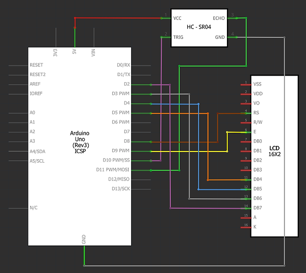
1) Ultrasonic Sensor to Arduino Uno:
-
VCC to 5V: Connect the VCC pin of the ultrasonic sensor to the Arduino's 5V pin.
-
GND to GND: Connect the GND pin of the ultrasonic sensor to the Arduino's GND pin.
-
Trigger to Pin 10: Connect the Trigger pin of the sensor to digital pin 10.
-
Echo to Pin 11: Connect the Echo pin of the sensor to digital pin 11.
IF USING THE 16x2 SHIELD, WIRE IT AS FOLLOWS
2) Connect the LCD to the Arduino:
-
The LCD Shield has a 5V pin and a GND pin (Located Right of the buttons) these must be connected to the Arduinos 5V and GND pin respectively.
-
The LCD has 16 pins. Wire them as follows:
-
Pin 1 (VSS): (GND '-') Leave unconnected, this is pre-routed via the Shields' board.
-
Pin 2 (VDD): (5V '+') Leave unconnected, this is pre-routed via the Shields' board.
-
Pin 3 (V0): (GND '+') Leave unconnected, this is pre-routed via the Shields' board.
-
Pin 4 (RS): Connect to Arduino digital Pin 8.
-
Pin 5 (RW): (GND '+') Leave unconnected, this is pre-routed via the Shields' board.
-
Pin 6 (E): Connect to Arduino digital Pin 9.
-
Pins 7-10 (D0-D3): Leave unconnected (for 4-bit mode).
-
Pins 11-14 (D4-D7): Connect to Arduino digital Pins 5, 4, 3, and 2 respectively.
-
Pin 15 (Backlight +): (5V '+') Leave unconnected, this is pre-routed via the Shields' board.
-
Pin 16 (Backlight -): (GND '-') Connect to common Arduino GND.
-
IF USING THE 16x2 STAND-ALONE LCD DISPLAY
-
The LCD has 16 pins. Wire them as follows:
-
Pin 1 (VSS): (GND '-') Connect to Arduino's common ground pin.
-
Pin 2 (VDD): (5V '+') Connect to the 5V line of the Arduino.
-
Pin 3 (V0): (GND '+') Connect to the 5V line of the Arduino.
-
Pin 4 (RS): Connect to Arduino digital Pin 8.
-
Pin 5 (RW): (GND '-') This pin dictates if the LCD will read/write. Connect to Arduino's common ground pin for write mode.
-
Pin 6 (E): Connect to Arduino digital Pin 9.
-
Pins 7-10 (D0-D3): Leave unconnected (for 4-bit mode).
-
Pins 11-14 (D4-D7): Connect to Arduino digital Pins 5, 4, 3, and 2 respectively.
-
Pin 15 (Backlight +): (5V '+') Connect to the 5V line of the Arduino through a 220Ω resistor.
-
Pin 16 (Backlight -): (GND '-') Connect to Arduino's common ground pin.
-
Software Setup
-
Use the Pre-Installed LiquidCrystal Library:
-
The standard LiquidCrystal library is pre-installed in the Arduino IDE. There is no need to install additional libraries.
-


CODE BREAK-DOWN
#include <LiquidCrystal.h>
-
Includes the LiquidCrystal library, which provides functions to control the 16x2 LCD.
LiquidCrystal lcd(7, 6, 5, 4, 3, 2);
-
Initializes the LCD object and assigns the pins: RS to pin 7, E to pin 6, D4 to pin 5, D5 to pin 4, D6 to pin 3, and D7 to pin 2.
const int trigPin = 9;
-
Defines digital pin 9 as the Trigger pin for the ultrasonic sensor.
const int echoPin = 10;
-
Defines digital pin 10 as the Echo pin for the ultrasonic sensor.
void setup() {
-
The setup() function runs once when the program starts and initializes the settings.
pinMode(trigPin, OUTPUT);
-
Configures the Trigger pin as an output to send ultrasonic pulses.
pinMode(echoPin, INPUT);
-
Configures the Echo pin as an input to receive reflected ultrasonic pulses.
lcd.begin(16, 2);
-
Initializes the LCD with 16 columns and 2 rows.
lcd.print("Ultrasonic Ready");
-
Displays the text "Ultrasonic Ready" on the LCD as a startup message.
delay(2000);
-
Pauses for 2 seconds to allow the startup message to be visible.
lcd.clear();
-
Clears the LCD display for new content.
}
Ends the setup() function.
void loop() {
-
The loop() function runs continuously, performing the main tasks.
long duration = measureDistance();
-
Calls the measureDistance() function to measure the Echo signal duration and stores the result in duration.
float distance = duration * 0.034 / 2;
-
Converts the measured duration into distance in centimeters using the speed of sound.
lcd.setCursor(0, 0);
-
Sets the cursor to the first column of the first row on the LCD.
lcd.print("Distance:");
-
Displays the label "Distance:" on the first row of the LCD.
lcd.setCursor(0, 1);
-
Sets the cursor to the first column of the second row on the LCD.
if (distance >= 2 && distance <= 400) {
-
Checks if the calculated distance is within the valid range of the sensor (2 to 400 cm).
lcd.print(distance);
-
Displays the distance value on the second row of the LCD.
lcd.print(" cm");
-
Appends " cm" to the distance value for clarity.
} else {
Executes the following code if the distance is outside the valid range.
lcd.print("Out of range");
-
Displays "Out of range" on the second row of the LCD when the distance is invalid.
}
Ends the if-else statement.
delay(500);
-
Pauses for 500 milliseconds before the next reading.
}
Ends the loop() function.
long measureDistance() {
-
Defines the measureDistance() function, which calculates the duration of the Echo signal.
digitalWrite(trigPin, LOW);
-
Sets the Trigger pin LOW to stabilize the signal before sending a pulse.
delayMicroseconds(2);
-
Pauses for 2 microseconds to ensure stability.
digitalWrite(trigPin, HIGH);
-
Sets the Trigger pin HIGH to send an ultrasonic pulse.
delayMicroseconds(10);
-
Holds the HIGH state for 10 microseconds, generating a valid ultrasonic pulse.
digitalWrite(trigPin, LOW);
-
Stops the pulse by setting the Trigger pin LOW.
return pulseIn(echoPin, HIGH);
-
Measures the duration of the Echo pin’s HIGH state, which corresponds to the round-trip time of the ultrasonic pulse, and returns the value.
}
Ends the measureDistance() function.